Overview Product Structure Advantages & Features Technical Specifications Request a Proposal

Product Overview

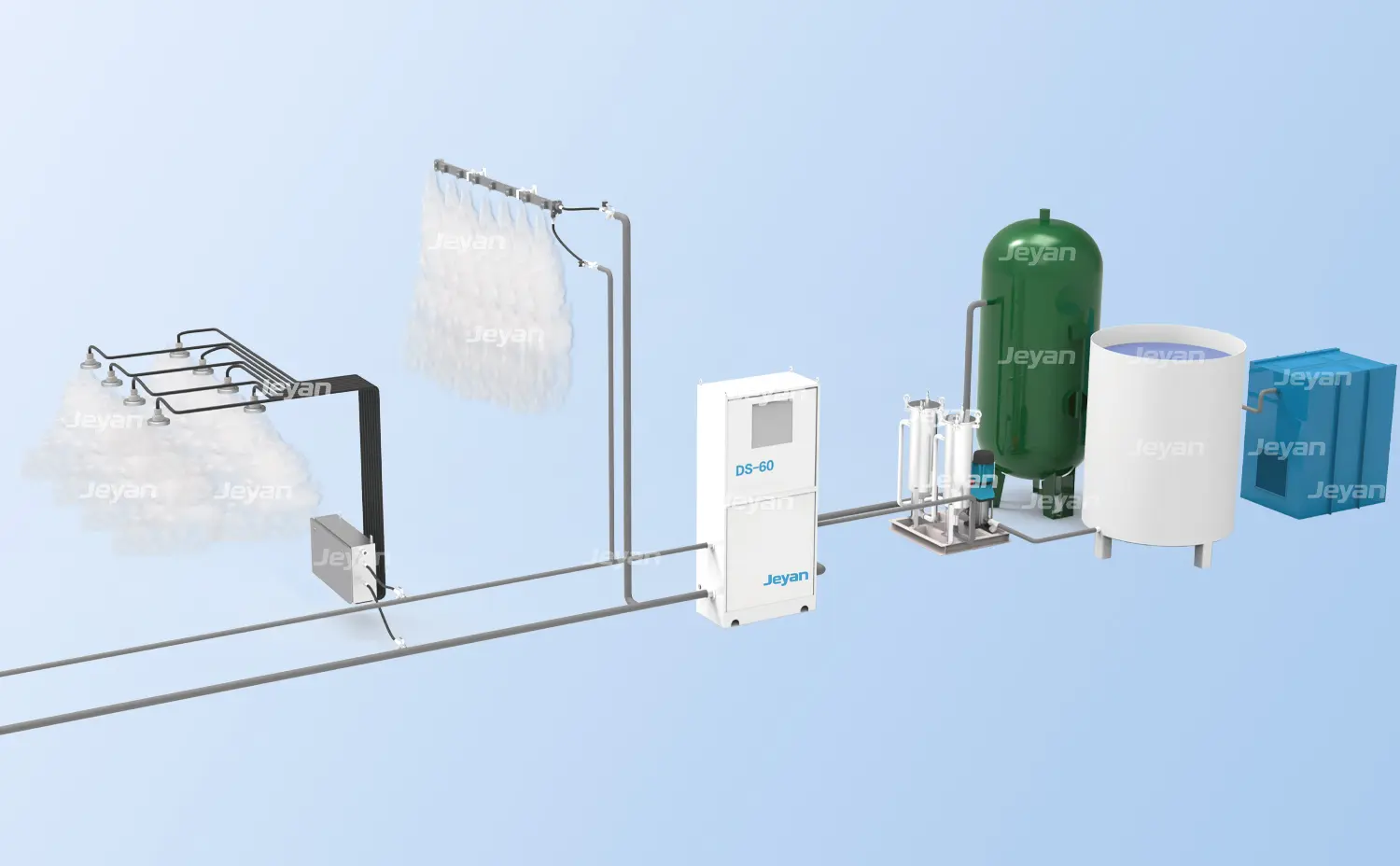
The Dry Fog Dust Suppression System is designed for controlling fugitive dust generated during bulk material handling processes such as crushing, conveying, loading, unloading, and storage.

The system produces fog droplets typically in the range of 1–10 microns, similar in size to respirable dust particles. These droplets collide and agglomerate with airborne dust, causing them to settle quickly back into the process stream. Compared with traditional water spray systems, dry fog technology significantly reduces water consumption and avoids material over-wetting.

Droplet size
1-10 microns
Spray Distance
Up to 5 meters
Application
Conveyor transfer points,Truck loading stations,Crusher plants,Screening plants,Stockpile handling

Product Structure

The dry fog dust suppression system is composed of integrated modules covering control, water supply, air-water distribution, and spray execution.

Each component is designed to work in coordination, ensuring stable pressure control, precise air-water mixing, and consistent atomization performance across different operating conditions.

  • ① Air Compressor
  • ② Compressed Air Tank
  • ③ Water Tank
  • ④ Water Filter
  • ⑤ Constant Pressure Pumping System
  • ⑥ Main Control Unit
  • ⑦ Adjustable Spray Nozzle Mount
  • ⑧ Water-gas Distribution device
  • ⑨ Spray Manifold Assembly

Key Modules & Advantages

The dry fog dust suppression system is built around several key modules, each performing a specific function within the overall process.

Main Control Unit

The Main Control Unit serves as the central control core of the dry fog system.

It manages system start and stop operations, monitors water and air pressure in real time, and triggers alarms or automatic shutdown when pressure drops below preset thresholds. The unit can receive remote control signals and process interlock inputs such as material flow or conveyor operation signals to control individual or grouped water-gas distribution devices.

The enclosure is available in powder-coated carbon steel or stainless steel, with stainless steel internal piping. The control system is based on a Siemens PLC platform, ensuring stable and reliable operation.

Main Control Unit

Constant Pressure Pumping System

The Constant Pressure Pumping System ensures stable water supply under varying operating conditions.

It consists of a water pump, pressure transmitter, buffer tank, and frequency inverter. The system automatically adjusts pump speed based on real-time pressure feedback to maintain a constant outlet pressure.

Even when the number of active spray nozzles changes, the system maintains stable pressure output, ensuring consistent atomization performance. An alarm is triggered if the pressure remains below the set value for an extended period.

Constant Pressure Pumping System

Water-Gas Distribution Device

The Water-Gas Distribution Device is responsible for distributing and regulating both water and compressed air.

A single inlet of water and air is divided into multiple outlets (typically 4, 6, or 8 lines), each supplying individual spray nozzles. The unit integrates pressure regulators for both water and air, allowing independent adjustment to optimize atomization performance.

Built-in solenoid valves enable automatic control of each branch line, allowing the system to activate or deactivate specific spray zones based on operating conditions. The housing and internal piping are typically made of stainless steel for durability and corrosion resistance.

Water-Gas Distribution Device

Spray Manifold Assembly

The Spray Manifold Assembly forms a continuous spray barrier across the target area.

Multiple nozzles are arranged along a common manifold, enabling simultaneous spraying to create a uniform fog curtain. This configuration effectively captures and suppresses airborne dust, preventing its dispersion into the surrounding environment.

The modular length of the manifold allows adaptation to different installation widths and coverage requirements.

Spray Manifold Assembly

Adjustable Spray Nozzle Mount

The Adjustable Spray Nozzle Mount provides flexible installation and directional control of the spray pattern.

Typically installed above conveyor transfer points or chute inlets, the mount allows operators to adjust the spray angle and position according to site conditions. This ensures optimal coverage of dust generation zones and improves overall dust suppression efficiency.

Adjustable Spray Nozzle Mount

Main Advantages

● Dry fog dust suppression delivers efficient dust control with minimal resource consumption and no impact on material quality.

● Ultra-low water consumption – significantly reduces water usage compared to conventional spray systems

● No material wetting – micron-sized droplets evaporate quickly, avoiding moisture addition to bulk material

● No secondary pollution – captured dust returns directly to the material stream, eliminating wastewater or sludge handling

● High dust suppression efficiency – fine droplets effectively agglomerate airborne dust at the source Flexible and energy-efficient operation – adapts to varying operating conditions with stable performance and low energy demand

Technical Specifications

Typical technical data of standard models are shown below for reference and preliminary selection.

Model SV-30 SV-60 SV-81
Water Consumption 45 L/h 20 L/h 7.1 L/h
Air Consumption 260 L/min 240 L/min 115 L/min
Water Supply Pressure 0.1–0.2 MPa 0.1–0.2 MPa 0.1–0.2 MPa
Air Supply Pressure 0.3–0.5 MPa 0.3–0.5 MPa 0.3–0.5 MPa
Atomization Particle Size ≤10 μm ≤10 μm ≤10 μm

* Capacity based on typical bulk density, data for reference only, final design prevails, dimensions subject to configuration.

Frequently Asked Questions

Common questions about application range, dust control, and selection data.

Q: What materials can the TA loading spout handle?

A: It is designed for dry bulk material loading into open trucks and rail cars, and can be configured for different wear and corrosion conditions through material and lining options.

Q: How is dust controlled during loading?

A: The outlet uses a double-layer rubber dust skirt with automatic lifting to stay close to the material pile, and the spout also has a dust collection port for connection to an extraction system.

Q: What data is needed for selection?

A: Please provide material type, capacity, loading point, truck or rail car type, wear/corrosion condition, dust control target, and any control or automation requirements.